


Specific or complex project ahead? Get in touch for a free, fast quote.
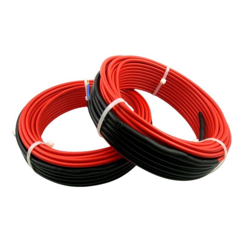


15W/m In-Screed Electric Underfloor Heating Cable
Regular price
£59.95
Inc. VAT
£49.96
Exc. VAT
FREE Express Delivery (1-3 days) in UK Mainland on most orders*
Excluding: Solar Panels (£170 delivery / free above £2,500), Batteries (£39 delivery), Small Items (£4.95/5.95 delivery / free above £500)
Contact Us to check for Next Working Day Delivery or Same-day Delivery options
Contact Us for Click & Collect options
Custom quote available on request
*See checkout or shipping policy for full details
Payment options
Tools & Kits
Build your kit
Need a full system?
Design your complete solution in minutes with our kit builders.
Do you have a question
about this product?
One of our expert advisors will be happy to help you!
Contact Us
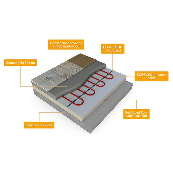
In-Screed Underfloor Heating Cable is a 15W per linear metre, 230V, single-core heating cable made for new-build screeded floors. It is laid on foil-faced insulation and covered with a minimum 50mm sand and cement screed, giving an economical whole-floor heating solution for kitchens, bathrooms, living areas and conservatories.
The cable has a full metallic earth screen, XLPE core insulation and a tough PVC outer sheath, so it is earthed and suitable for wet areas such as bathrooms and kitchens. It works under all floor finishes (tile, stone, vinyl, carpet, wood and laminate) and comes in 16 cable lengths from 200W to 3,400W with 2 × 5m factory-fitted cold tails. Changing the spacing between cable runs lets you design for 100, 130, 160 or 200W/m², from background tile warming to high heat loss rooms.
15 W/m
Heating cable output
230 V
Mains supply
200–3,400 W
16 cable sizes
100–200 W/m²
Design output range
50 mm
Minimum screed cover
10 years
Cable guarantee
Electrical safety and testing
Final connections to the mains supply and the thermostat must be made by a qualified electrician, and the installation must be protected by a 30mA RCD. Check the cable resistance against the label value and measure the insulation resistance before and after covering the cable with screed, record the values on the guarantee certificate, and carry out a further insulation test in accordance with BS 7671. Report any discrepancy to us immediately and stop work.
Designed for new screed floors
The cable must be covered by at least 50mm of sand and cement screed and must never be cut, shortened, crossed or allowed to touch itself. Only the cold tails may be shortened. Do not place cable under permanently fixed furniture or fittings such as kitchen units or baths. Allow the screed to dry fully before switching on (about 4–6 weeks; follow the screed manufacturer's instructions). The orange PVC sheath has no UV protection, so keep the cable out of direct sunlight until it is covered.
Key features
Full metallic earth screen
A tinned copper wire and AL/PET foil screen wraps the conductor for total safety, and the earthed cable is suitable for bathrooms and kitchens.
Tough double protection
XLPE insulation around the conductor plus a PVC outer sheath protect the cable during installation and extend its working life.
Four design outputs
Space the cable at 7.5 to 15cm centres to achieve 100, 130, 160 or 200W/m² to suit tile warming, comfort heating or high heat loss areas.
Economical for new builds
At 15W per linear metre it heats a whole screeded floor with fewer cable runs than lower-output cables, laid straight onto insulation.
All floor finishes
Suitable under tile, stone, vinyl, carpet, wood and laminate in both wet and dry areas.
Ready to connect
2 × 5m cold tails are factory fitted to the heating cable, so your electrician can connect straight to the thermostat. The cold tails can be shortened if needed.
Heat output guide
Choose the design output for the room, then set the centre-to-centre (C-C) spacing of the cable runs to match. The cable is rated at 15W per metre.
How to calculate your spacing
C-C spacing (cm) = free floor area (m²) × 100 ÷ cable length (m). Free floor area is the usable floor space less roughly 10% for the perimeter allowance. Alternatively, C-C spacing (cm) = cable output (15W/m) × 100 ÷ required output (W/m²). Keep at least 30mm between cable runs and leave a 50mm clearance from perimeter walls.
Cable sizes and coverage
Select the cable by total output (W) and the floor area it will cover at your chosen design output. Lengths are nominal.
Technical specifications
Guarantee conditions
The guarantee covers faults in material only. It is valid only when the installation completion certificate in the manual is completed, signed by the electrician and returned within 10 days, and the sealing cement procedure specified by its producer has been followed. It does not cover faults caused by incorrect design or installation, damage caused by others, or secondary charges for repairing or replacing floor coverings.
Installation overview
Read the full manual supplied with the cable before you start. In summary:
1
Prepare the sub-floor
Sweep the sub-floor clean and remove any sharp objects. If you are laying onto foil-faced insulation, make sure it is dust free so the fixings hold. Sketch your laying pattern and mark the positions for the floor sensor, connection box and thermostat.2
Fix the bands
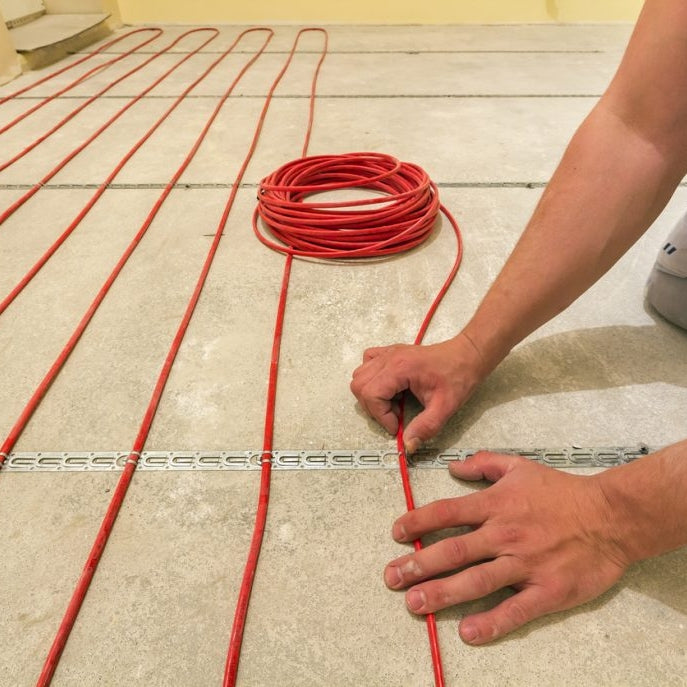
Fix the fixing band to the sub-floor or insulation at 750mm intervals using fixing nails or high-impact adhesive tape, leaving a 50mm border around the perimeter.3
Lay the cable
Keep the cable on its drum until you lay it, as unwinding it first makes it twist. Lay the orange heating cable to your spacing so runs never touch or cross, and do not cut or shorten it. Do not bend or strain the joint between the heating cable and the cold tail.4
Position the floor sensor
Place the sensor in its black flexible conduit between two heating cable loops, about 500mm from the wall.5
Test and screed
Check the cable resistance against the label value, then cover with at least 50mm of sand and cement screed. Wear rubber-soled boots, avoid unnecessary traffic over the cable, and tell other trades not to walk on it.6
Let the screed dry
Allow roughly 4–6 weeks for the screed to dry completely before the system is switched on.7
Connect and commission
A qualified electrician makes the final connections and installs the thermostat, checks the floor sensor continuity, retests the cable resistance and carries out a further insulation test. Complete and sign the guarantee certificate.Frequently asked questions
BTU & WATT Calculator
Room Dimensions
Room Type
Living Room
Bedroom
Kitchen
Bathroom
Conservatory
Hallway
Glazing Type
Single Glazed
Double Glazed
Triple Glazed
External Walls
0 Wall
1 Wall
2 Walls
3 Walls
4 Walls
Insulation Level
Poor
Average
Good (New Build)
Required Heating
0
Watts
0
BTUs
Tools & Kits
Build your kit
Need a full system?
Design your complete solution in minutes with our kit builders.
Do you have a question
about this product?
One of our expert advisors will be happy to help you!
Contact Us